This project aims to design and simulate a microstrip line quarter-wave transformer for matching a
| Parameter | Value |
|---|---|
| Strip thickness (M2) | 17 µm |
| Dielectric thickness (d) | 600 µm |
| Ground thickness (M1) | 17 µm |
| Dielectric material parameters (Polyethylene) | εr = 2.4, μ = μ0, σ = 0 |
| Metal conductivity (Copper) | σ = 5.8 × 10⁷ S/m |
Theoretical Calculations
A quarter-wave transformer matches two real impedances by using a transmission line of length and characteristic impedance . For this design, the target characteristic impedance for the quarter-wave transformer is .
For a given characteristic impedance and dielectric constant , the strip width to dielectric thickness ratio of a microstrip line can be calculated as
where
For this design, and . Plugging these values into the equation, while
The effective dielectric constant of a microstrip line is given approximately by
For this design, . Given the dimensions of the microstrip line, the characteristic impedance can be calculated as
For this design,
Considering a microstrip line as a quasi-TEM line, we can determine the attenuation due to dielectric loss as
where is the loss tangent of the dielectric material. For this design, dielectric material is lossless so the loss tangent , thus the attenuation due to dielectric loss is .
The attenuation due to conductor loss is given approximately by
where is the surface resistance of the conductor. For this design, and the attenuation due to conductor loss is .
The phase constant is given by where is the free-space wavenumber. For this design, the phase constant is .
The distributed model parameters of the microstrip line can be calculated as
where is the phase velocity of the wave on the microstrip line and
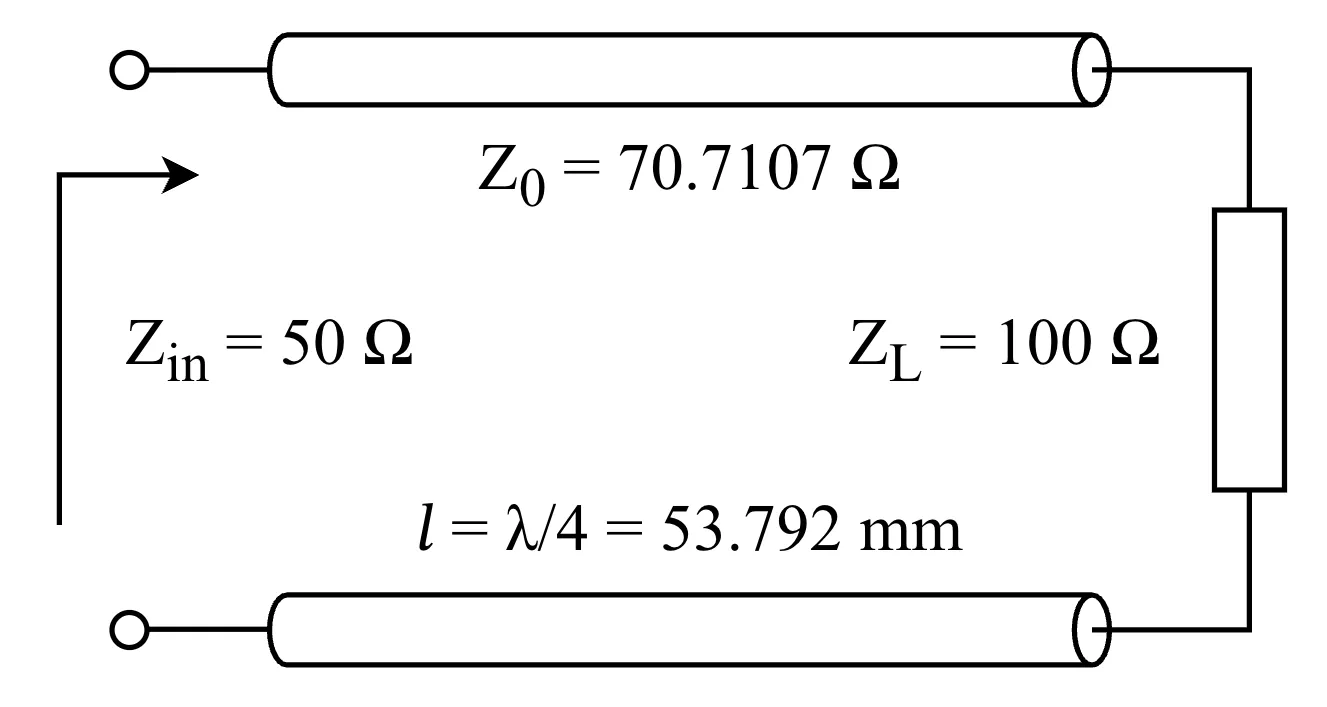
The wavelength inside the microstrip line can be calculated as . For this design, the wavelength is . Therefore, the length of the quarter-wave transformer is .
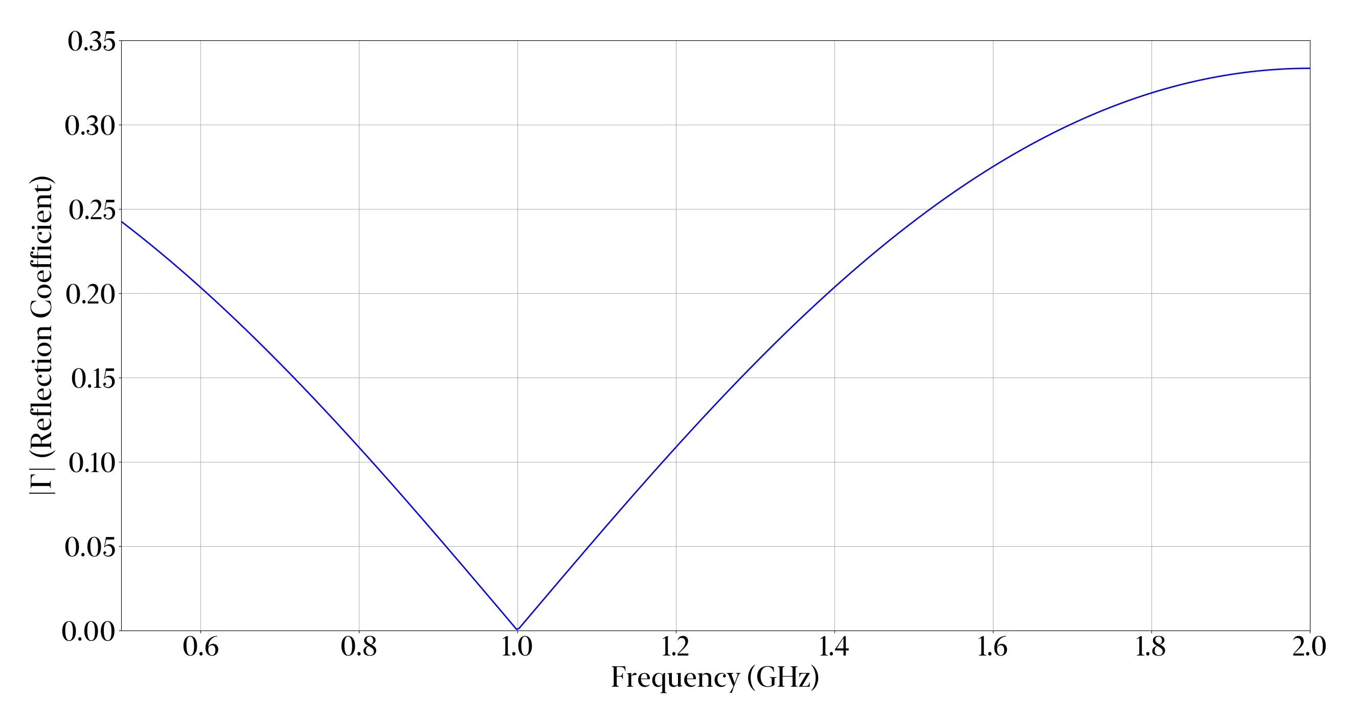
The reflection coefficient at the input of the quarter-wave transformer can be calculated as
The input impedance looking into a transmission line of length is
At , the line length is exactly , thus and . Then the input impedance simplifies to . Therefore, the reflection coefficient
| Parameter | Value | Parameter | Value |
|---|---|---|---|
| Strip Width | 995.06 µm | Strip Length | 53.792 mm |
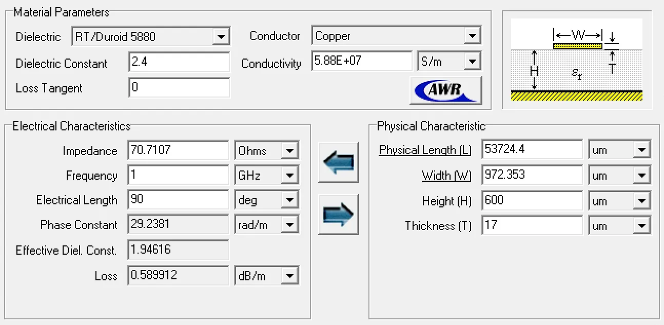
| Z0 | 70.7107 Ω (71.032 Ω) | εe | 1.944 |
| ⍺d | 0 | ⍺c | 0.1167 Np/m |
| β | 29.201 rad/m | Γ @ 1 GHz | 0 |
| R’ | 16.582 Ω/m | L’ | 330.12 nH/m |
| G’ | 0 S/m | C’ | 65.428 pF/m |
Simulation Results
For electromagnetic simulation, TXLine tool was used to validate the analytical calculations. TXLine parameters matched the theoretical design with small deviations, verifying the theoretical calculations.
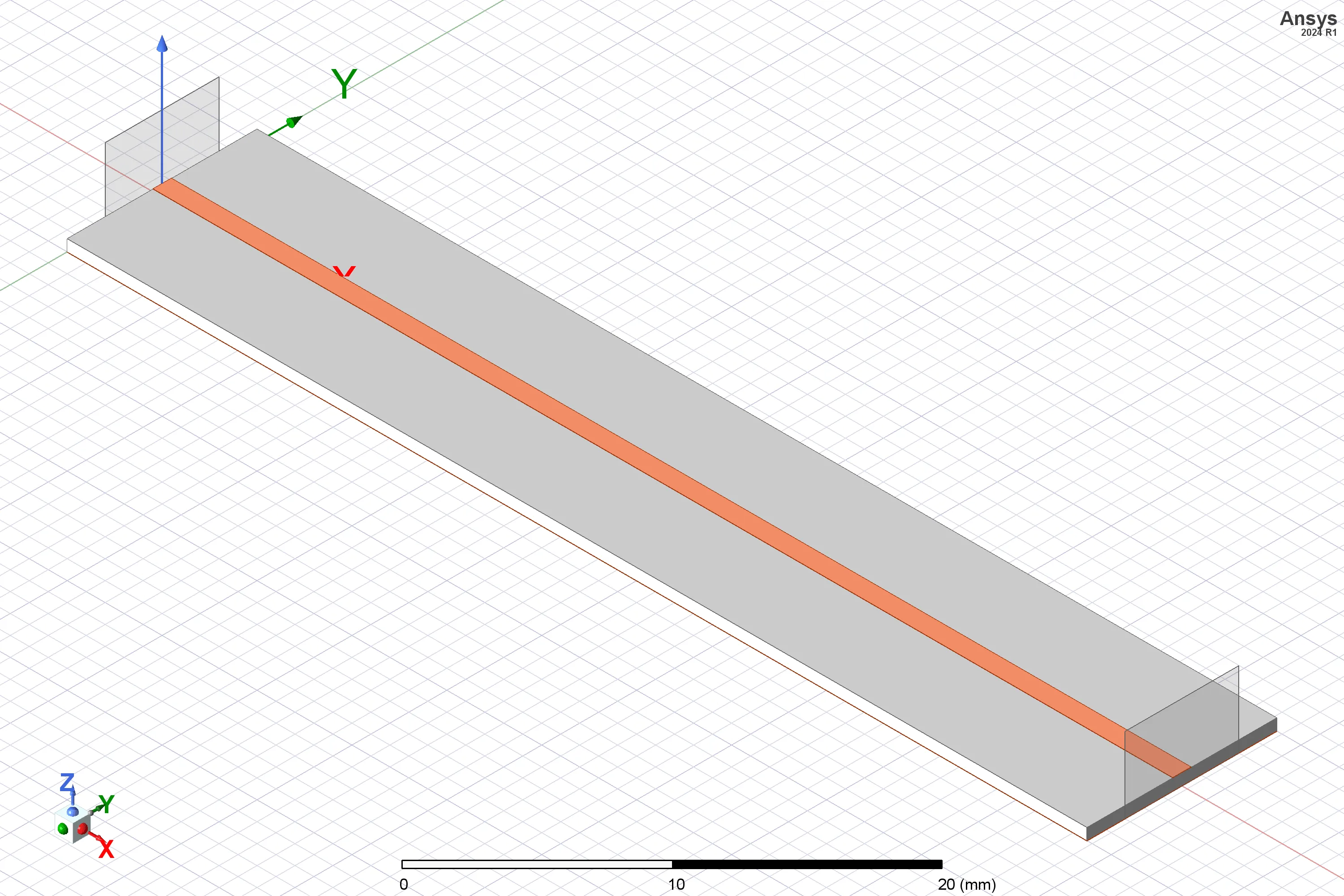
The 3D model was constructed in Ansys HFSS using design parameters and corresponding material properties.
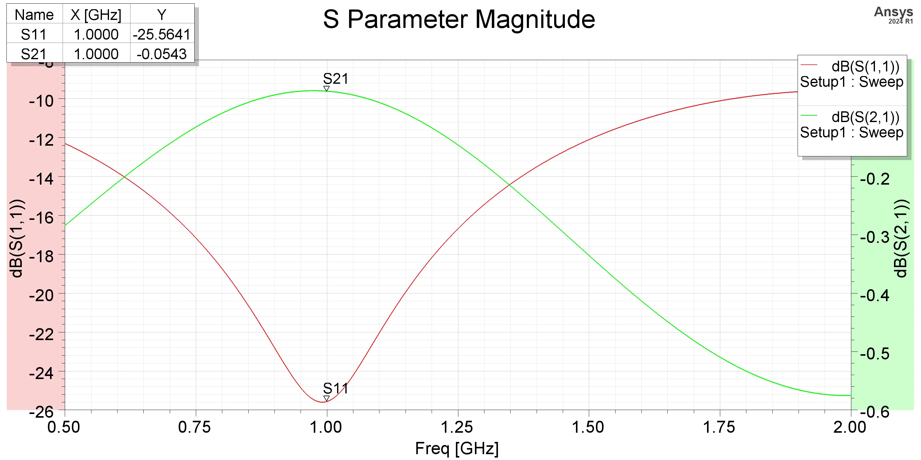
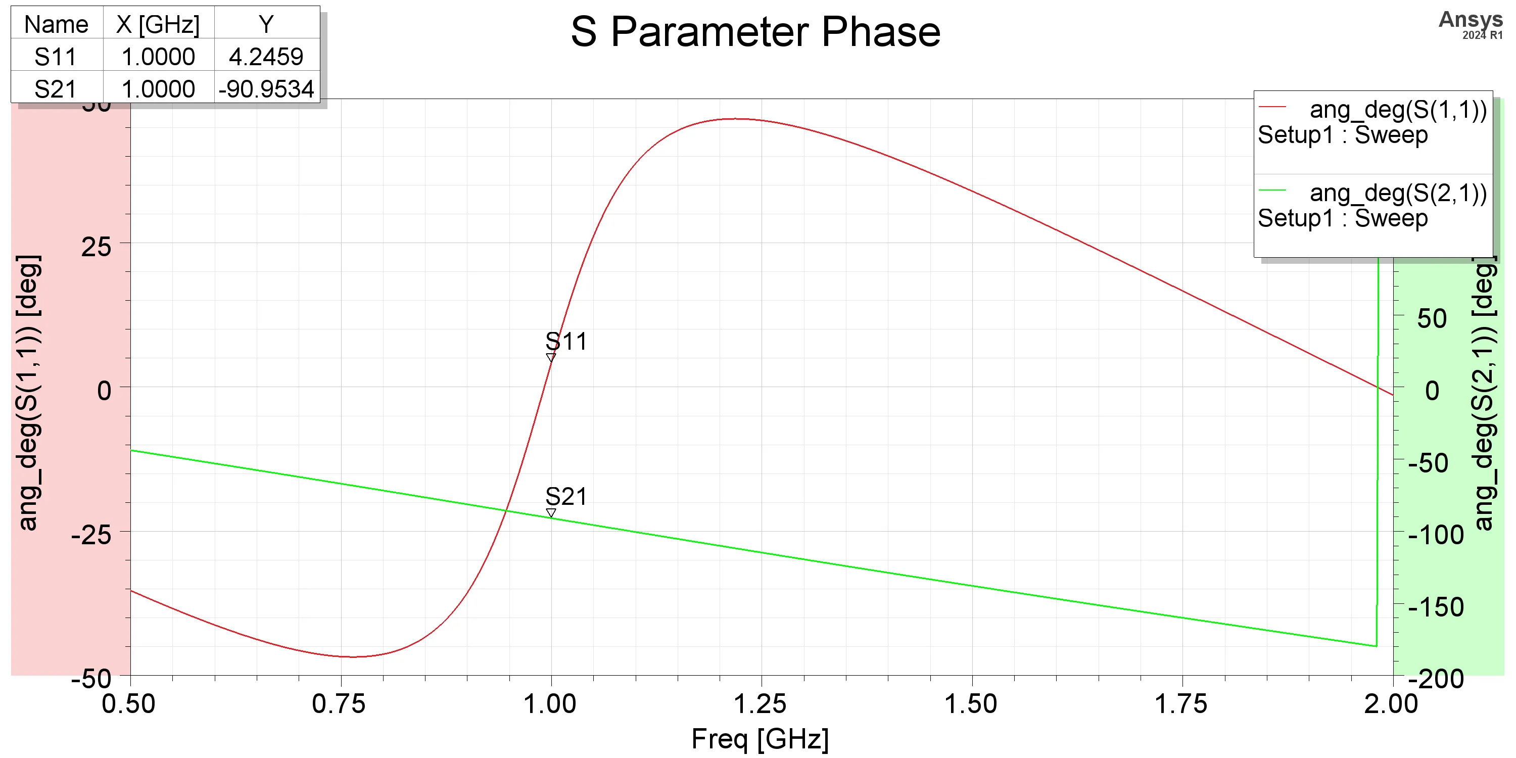
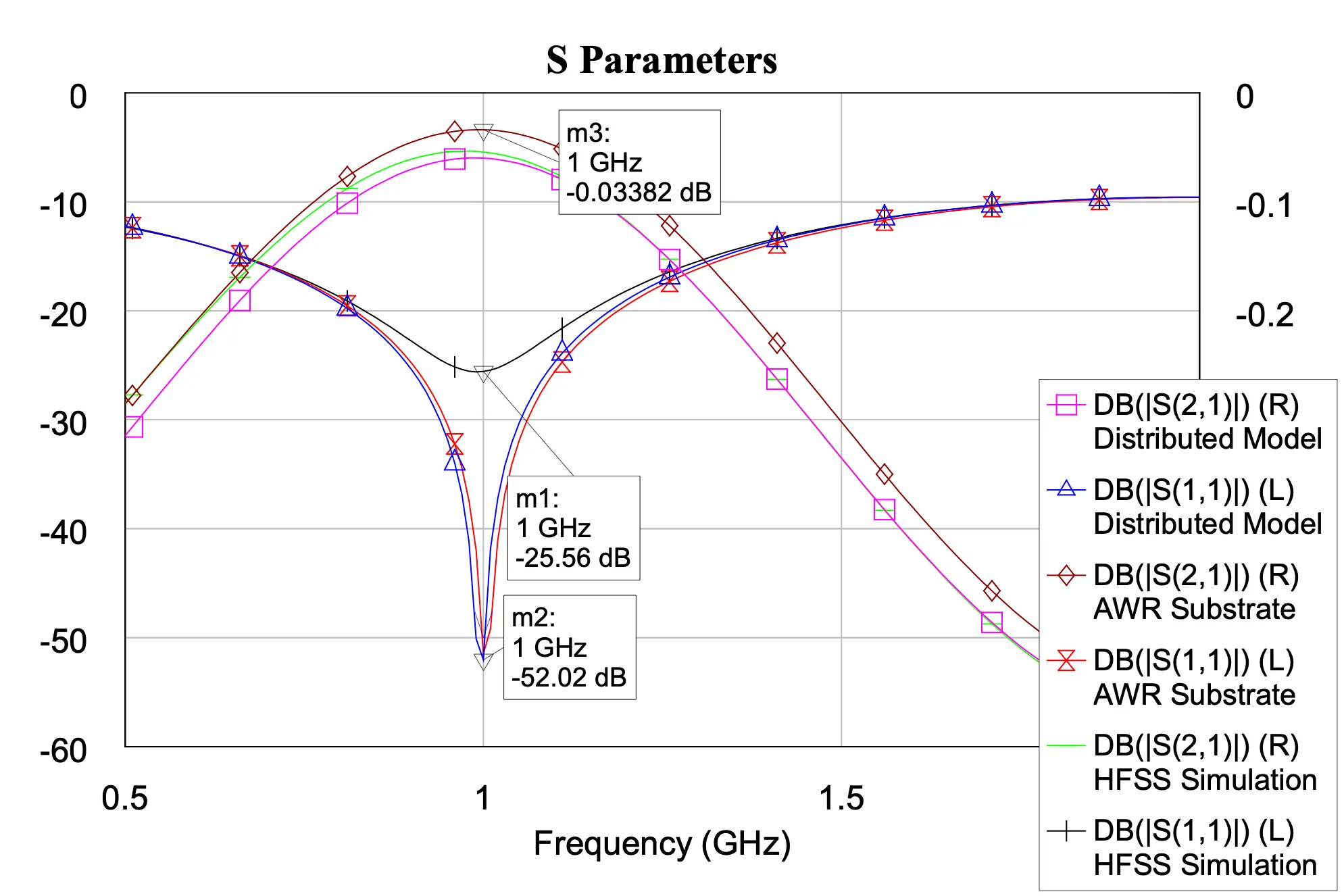
From the scattering parameters, the reflection at 1 GHz is -25.56 dB, and the insertion loss is 0.054 dB, indicating good impedance matching and low loss at the center frequency. The phase plot shows a phase shift of 90 degrees at 1 GHz, consistent with the expected behavior of a quarter-wave transformer. The results from the simulation closely align with the theoretical predictions, confirming the validity of the design and calculations.
From the simulation, the parameters are extracted as follows
| Parameter | Value | Parameter | Value |
|---|---|---|---|
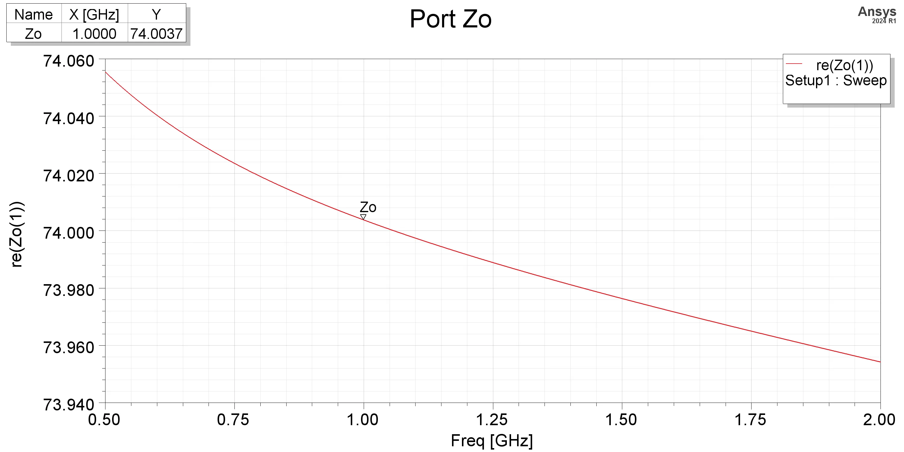
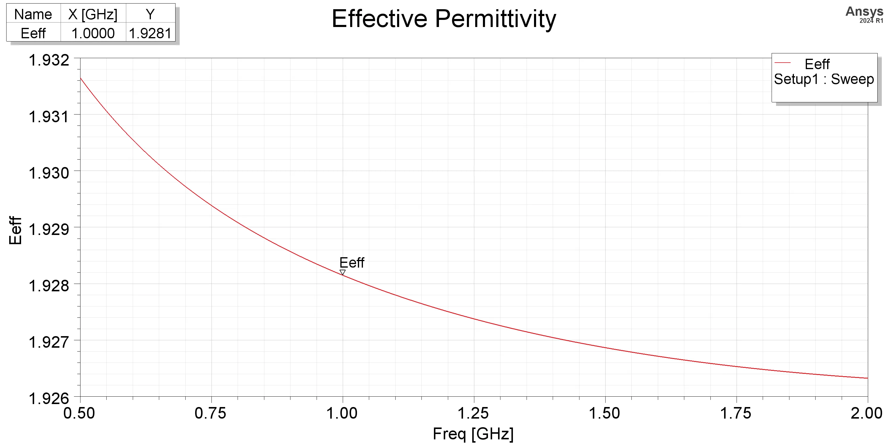
| Z0 | 74.0037 Ω | εe | 1.944 |
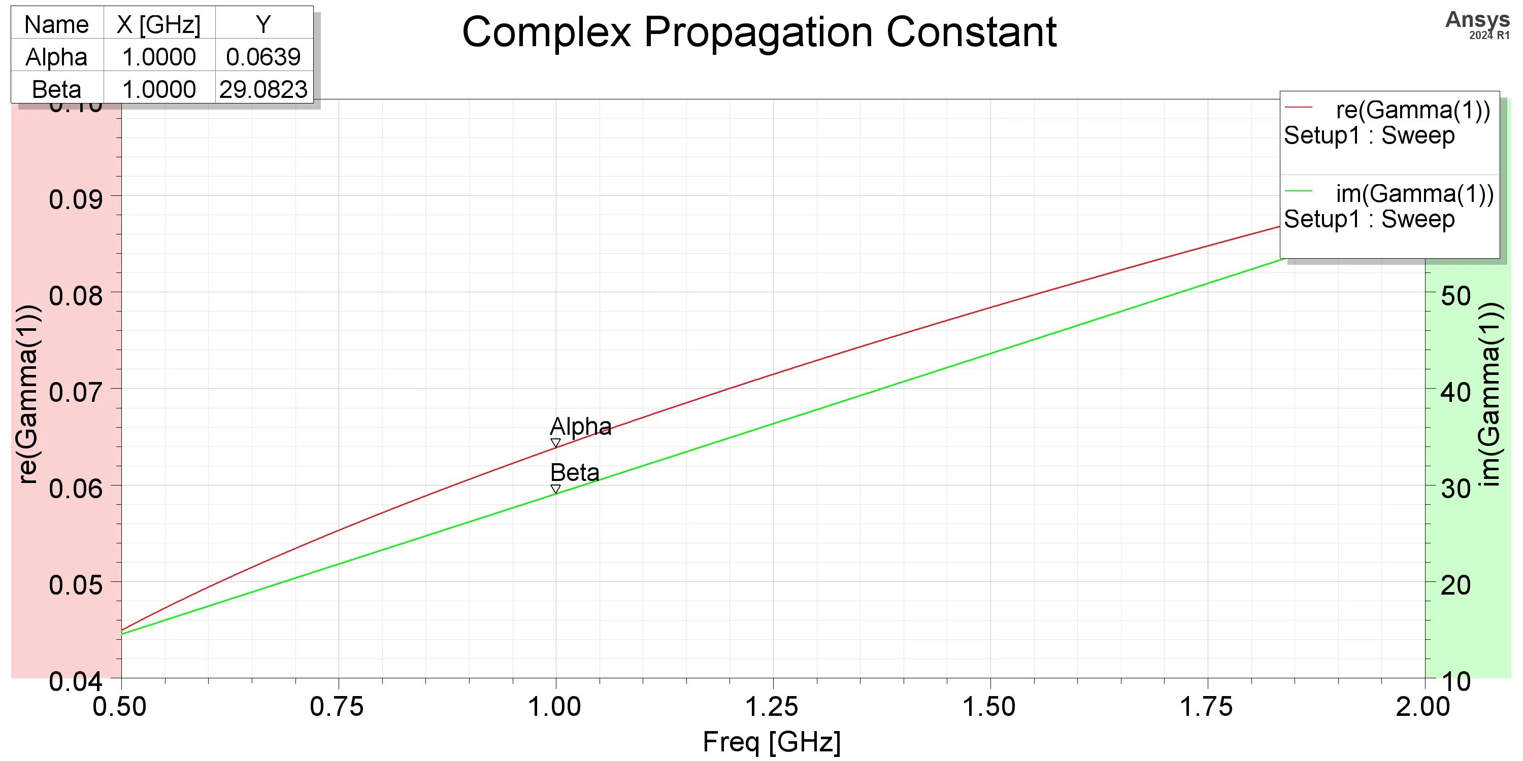
| ⍺ | 0.0639 Np/m | β | 29.0823 rad/m |
| S21 @ 1 GHz | -0.0543 dB | S11 @ 1 GHz | -25.56 dB |
The extracted parameters from the simulation match the theoretical calculations closely, indicating a successful design and simulation of the microstrip line quarter-wave transformer. The slight discrepancies can be attributed to the approximations made in the theoretical calculations, while the simulation accounts for more complex electromagnetic interactions and losses.
One notable observation is that the attenuation constant from the simulation (0.0639 Np/m) is approximately half the theoretical value calculated using the simplified parallel-plate model (0.1167 Np/m). This discrepancy arises because the simplified model assumes the current is constrained to the strip width W on both the top conductor and the ground plane. In the full-wave simulation, the return current on the ground plane spreads laterally beyond W, reducing the ground plane’s contribution to resistance. Consequently, the total loss is dominated by the strip conductor alone, resulting in a lower attenuation constant.
The distributed model was constructed with 50 cells in AWR Microwave Office using the calculated parameters.
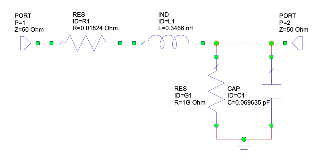
It can be observed that the S-parameters from the distributed model closely match the S-parameters from the full-wave simulation and the substrate simulation, confirming the validity of the distributed model and its parameters. The omission of the current crowding factor in the theoretical calculations is evident in the distributed model, when compared with the AWR substrate model simulation. Increasing the R’ parameter with respect to the crowding factor results in a near-exact match between the distributed model and the AWR substrate model, confirming the impact of the crowding factor on the attenuation constant.
It can also be seen that the S11 parameter from the HFSS simulation appears smoothed near the center frequency, while the S11 parameter from the distributed model and the AWR substrate model show a sharper dip at the center frequency. This can be attributed to the convergence limits of the FEM solver and the parasitic capacitance generated by the 3D fringing fields at the step discontinuity, which are not captured in the ideal circuit models.