Project Overview
This project implements a real-time amplitude and frequency modulation system based on Direct Digital Synthesis (DDS) on an ATmega328P microcontroller. The system generates digitally synthesized carrier signals and performs AM or FM modulation on the message signal received from the built-in ADC, and produces an analog output via PWM followed by an analog reconstruction filter.
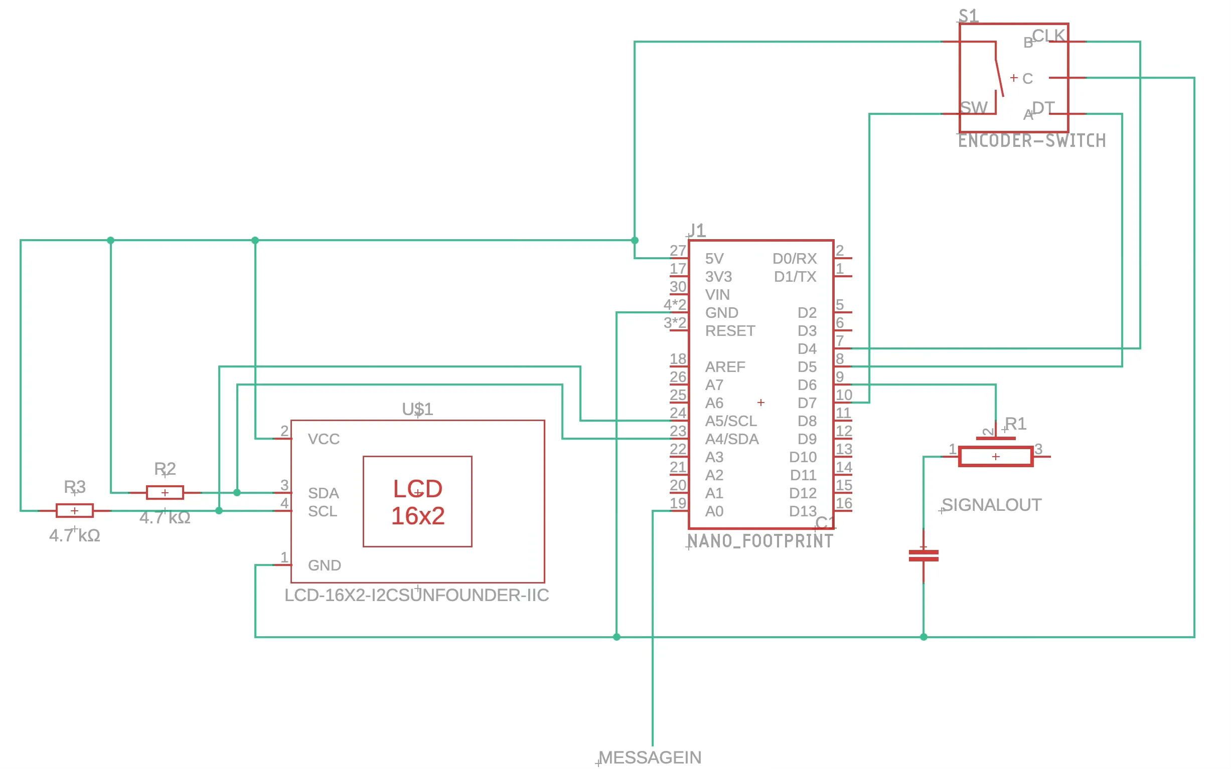
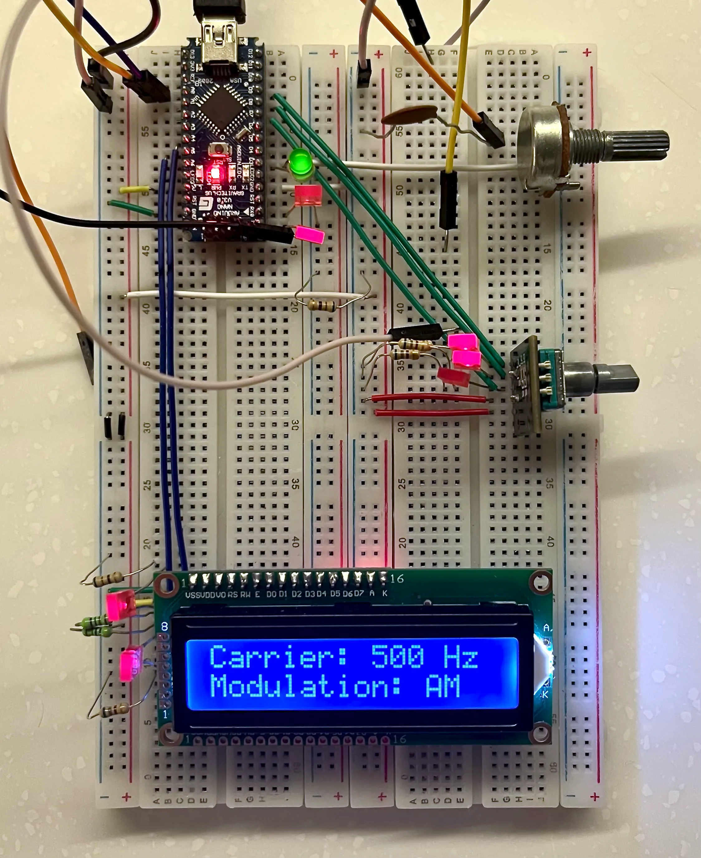
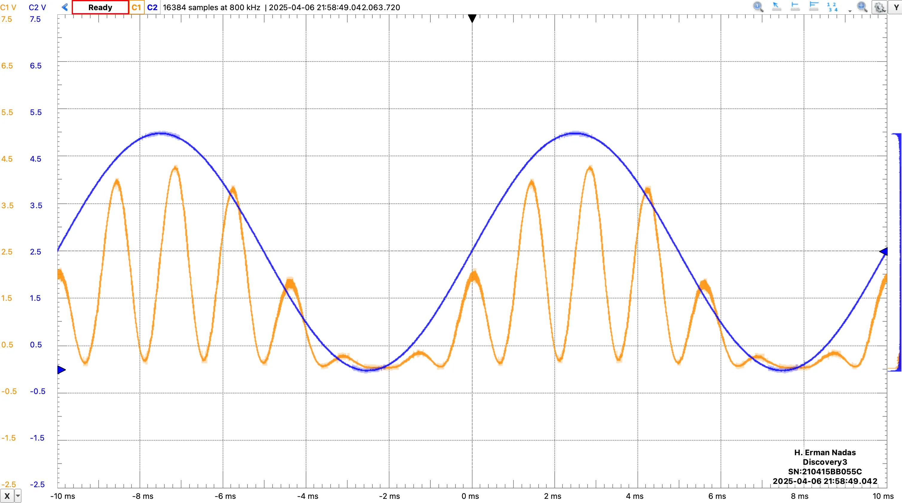
Pulse width is sampled at 20 kHz and is modulated at the required width to generate the desired analog signal. This output is then filtered using an RC low-pass filter with an adjustable cutoff frequency to remove high-frequency PWM component and construct the analog signal. Since the ATmega328P, a digital device, doesn’t have the capability of generating a negative voltage, the generated sine wave has a constant 2.5 V DC offset. The user can control the carrier frequency and the modulation type by a rotary encoder or UART interface. Feedback on the system’s current state is shown on a 16x2 LCD display.
System Implementation
Signal Generation with Direct Digital Synthesis
An interrupt timer set at 20 kHz is used to process the samples incoming from the ADC at 125 kHz sampling frequency. This interrupt service routine is also responsible for modifying a second PWM timer to produce the desired output signal. With the timer having a resolution of 8-bits, ADC is matched to this rate to eliminate the overhead of downsampling. With the internal sampling frequency and the filter design considered, the maximum carrier frequency is limited to 5 kHz.
The output signal is generated by traversing a 32-bit lookup table of sine wave values, indexed by a phase accumulator. The accumulated phase is the sum of the previous phase increment values, which is calculated based on the desired carrier frequency and the sampling frequency.
For amplitude modulation, variable in is simply set to the carrier frequency, and the output signal is scaled by the message signal from the ADC.
For frequency modulation, variable in is adjusted with respect to the message signal from the ADC. System has a fixed modulation index with 1 Hz / 2 mV. The ADC input is offset by 128 (2.5 V) and the frequency deviation is calculated at each ISR call, which then the phase increment is adjusted accordingly.
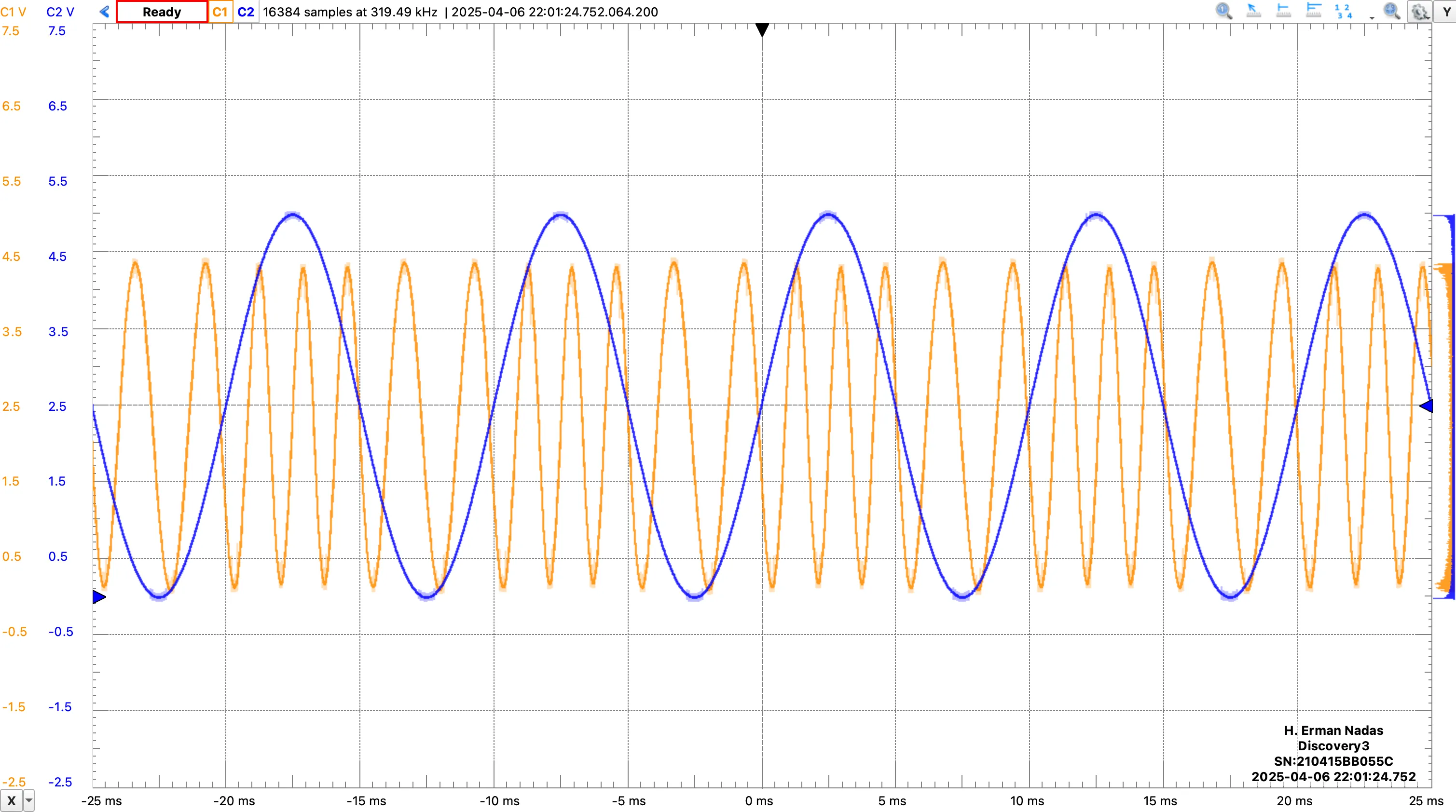
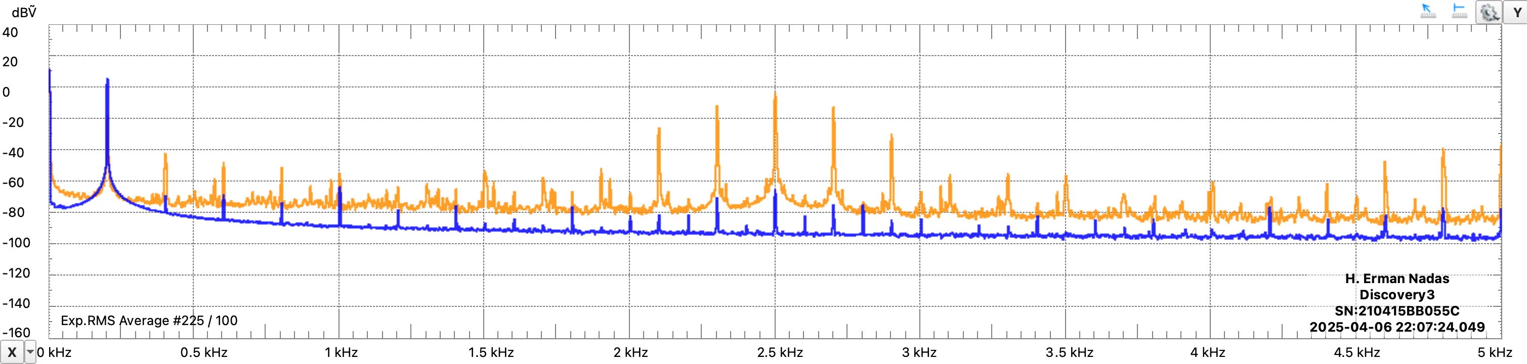
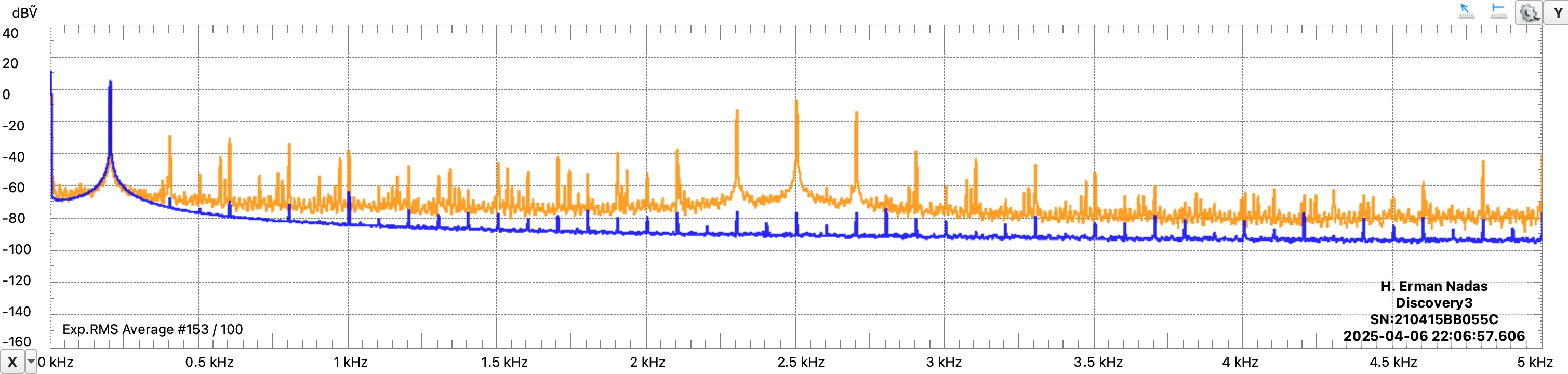
While significant noise and a number of spurs are visible in the frequency domain outputs, it is clear that the carrier and message signal components are the prominent features of the spectrum.
uint8_t dds_update(uint8_t message_sample) {
    static uint32_t dds_phase_accumulator = 0;
    static const uint8_t * sine_table = NULL;

    if (sine_table == NULL)
        sine_table = init_sine_table();

    if (dds_get_mode() == MODE_FM) {
        uint8_t adc_value = (message_sample > FM_ADC_CORRECTION) ? (message_sample - FM_ADC_CORRECTION) : 0;
        int16_t deviation = (int16_t)adc_value - 128;
        int32_t offset = (deviation * FM_DEVIATION) / 128;
        int32_t effective_freq = (int32_t)dds_carrier_frequency + offset;

        if (effective_freq < 1)
            effective_freq = 1;

        dds_phase_increment = dds_compute_phase_increment((uint16_t)effective_freq);
    }

    dds_phase_accumulator += dds_phase_increment;

    uint8_t carrier = sine_table[dds_phase_accumulator >> 24];

    if (dds_get_mode() == MODE_AM)
        return ((uint16_t)carrier * message_sample) / 255;
    else
        return carrier;
}
Sine Lookup Table Generation
To reduce the microcontroller overhead during generation, the sine lookup table is stored in the EEPROM to be kept between power cycles. To decide whether to generate the table or not, a “Magic Number” is kept in the EEPROM. If this magic number is valid (0xAA), the LUT is simply loaded from EEPROM to RAM.
If invalid, the LUT values are calculated and saved to the EEPROM. During this process, to protect the EEPROM’s write cycle life, values are read, compared, and written only if they differ. The C language internal math library is used when creating the sine table. However, the computationally heavy sine function is not used for every sample; instead, a single sample is calculated, and the rest is generated using trigonometric sum identities. For 8-bit resolution, calculating angles separated by $2\pi/256$ radians, the following identities are used:
User Interface and Peripherals
To provide effective and easy control of the system by the user, various methods and peripherals were utilized. All digital synthesis operations and peripherals are controlled via interrupt-based processes. Whenever a change occurs in the system, these processes send information using flags held in global variables to the process messages service running in the main loop. Detected changes are then communicated back to the user appropriately.
User Inputs and Feedback
The user can change the carrier signal frequency and modulation type using the rotary encoder or by communicating via UART from a connected host computer. For maximum safety of these external interventions, DDS data and operations are encapsulated. DDS functions and variables shared among them are defined in a separate C file, inaccessible from other files, and getter/setter functions are defined for access.
Situations such as the user entering an invalid command via UART or entering a frequency less than or equal to 0 Hz are reported back via error messages. If an invalid frequency is entered, the system continues as is. If a value higher than the maximum allowed carrier frequency (5 kHz) is entered, the carrier signal frequency is capped at the highest value. Any change in frequency and modulation type, whether from UART or the rotary encoder, is reported to the user. This current frequency and modulation mode information can be seen on the LCD screen.
USART Communication
Using the microcontroller’s USART unit, an 8-bit asynchronous UART communication at 9600 Baud is provided with a host computer. For UART transmission, a blocking method that waits for the data register to empty is used. Since UART transmission is not a frequent operation, this blocking method does not cause a performance loss.
However, UART data reception, being an operation that needs frequent checking, is implemented with a non-blocking, interrupt-driven method. The USART unit triggers an interrupt every time it receives data, continuously filling a command buffer until a Carriage Return (CR) + Line Feed (LF) is received. When CR+LF arrives, the interrupt terminates the buffer with a null character ('\0'), passes this string to the command processing service to apply the command, and updates the appropriate flags.
Rotary Encoder and Button
Pin change interrupts are used to process the rotary encoder, and no debouncing process was needed. The interrupt is masked to Port B pins 0 and 1. Each time the interrupt is triggered, the current state of the rotary encoder pins is recorded. When three consecutive encoder states match one of the valid sequences, the carrier frequency is adjusted. Valid sequences are typically 00,01,11 and 11,10,00 for a right turn; and 00,10,11 and 11,01,00 for a left turn. Due to a deformation in the used rotary encoder where ground and source were connected reversely, these matches were inverted. The control is intuitively designed to cause a 1 Hz increase for right turns and a 1 Hz decrease for left turns.
The encoder’s button is also processed using pin change interrupts, masked to Port D pin 7, but it required debouncing. A “system counter” embedded within the sampling timer is used for this. If the last detected change is greater than 1000 differences in the system counter, the button movement is processed. Since the sampling frequency is 20 kHz, 1000 differences correspond to a 50 ms debounce period. If a valid button variation is decided, the modulation mode is toggled on the rising edge.
LCD Screen
An I²C protocol operating at 100 kHz is used to control the LCD screen. The start function initiates communication by writing the appropriate address to the data bus. Since only the most significant 4-bits represent the sent data while the least significant 4-bits represent the LCD mode, data must be sent as 4-bit nibbles instead of bytes.
A function is written to initiate communication with the screen’s address, keeping the LCD backlight continuously open, and sending each nibble appropriately. Based on this, commands for initialization, clearing the display, and setting the cursor are generated. Finally, using all these functions, a routine to print the detected changes to the screen was formed, and this is used continuously in the process messages service.